Engine installation started with selecting an engine to match the airframe. For such a large plane, gas makes more sense than glow for fuel. Electric was not an option for this plane. The sound of a 4 stroke engine is so much sweeter than that of a 2 stroke. The smoothness of a multi-cylinder engine is preferred above that of a single cylinder. A radial engine was the first consideration, but the weight of the radial is a little more than I wanted for this plane. So I settled on the Saito FG61TS. Before this engine flies the Dauntless, I wanted a flying season or so to break in the engine. This also let me work out any issues that the engine installation may present. I started with a Kangke Howard DGA plane as the airframe to break in the plane, but an engine failure did in that airplane. After figuring out the engine issue, the next airframe was a Great Planes Giant Stik XL. This turned out to be a great plane/engine combination. So much that I bought a second engine to replace this one when it goes into the Dauntless.
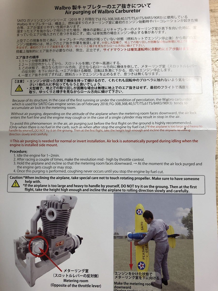
So what was the big issue with the engine? The carburetor. When you receive the engine from Saito, this sheet is included with the engine:
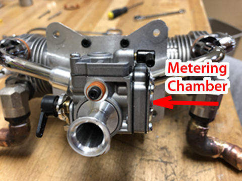
So the metering chamber is on the side of the carburetor and accumulates air and vapor. When the air or vapor is ingested into the engine, you get a sputter and cough. Sometimes (in the case of the Howard DGA) you get an engine out at an inconvenient time, such as right after take off. Saito's solution is to pick the plane up while the engine is running and rotate 90 degrees so the metering chamber is on the bottom. Hold this for a minute or two and you're good to go. Not something I want to do with a giant scale plane. So Saito's alternative solution is to fly the plane high and roll it until all the air is vented. I didn't like this option either.
Why not just rotate the carb 90 degrees, so the metering chamber is on the bottom...problem solved. Except you can only rotate the carb 180 degrees, which moves the metering chamber from the right side to the left side. In order to rotate 90 degrees, I made an adapter plate.
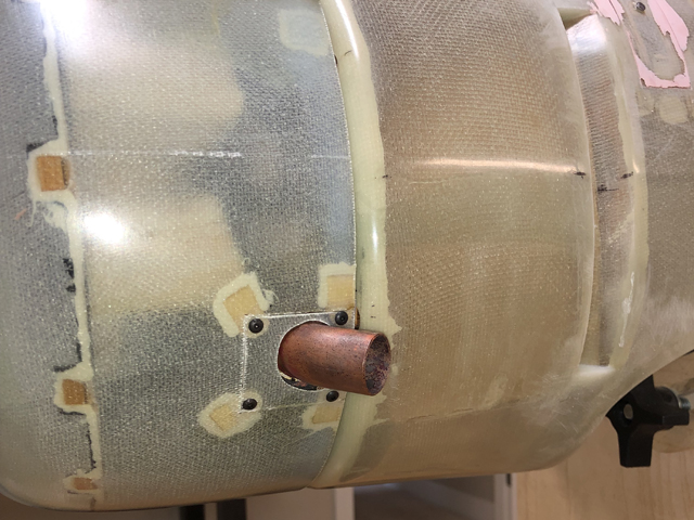
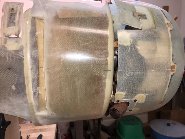
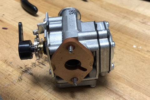
Here is the metering chamber location on the as-received engine, view from the rear and top:
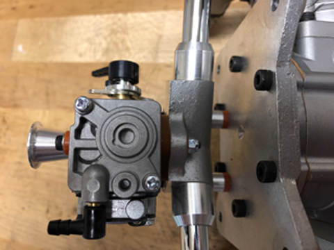
On the top view, note the phenolic spacer between the carb and the intake manifold. There are also a couple of phenolic spacers around the two bolts that secure the carb to the manifold. We will need an extra set of phenolic spacers and gaskets (Saito P/N SAIG3691).
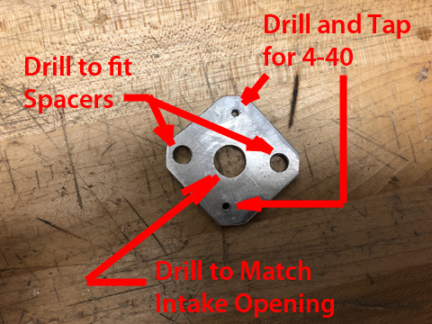
The adapter plate itself is cut from 1/8" thick aluminum. Drill a center hole to match the bore of the intake manifold. Then drill two holes to fit the phenolic spacers around the bolt holes. 90 degrees from these holes, drill and tap two holes for 4-40 thread.
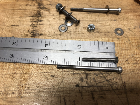
With one set of phenolic spacers and two gaskets (one on each side of the phenolic spacer) mount the adapter plate to the intake manifold. I used two 1" screws and 4-40 nuts with nylon inserts.
![]()
Notice how the screw heads are not flush with the adapter surface. The next phenolic spacer and one gasket is slightly trimmed to accommodate these screw heads. The flanges on the bolt spacers are cut off and then glued into the spacer that will go between the carb and adapter plate.
![]()
Using the modified spacers and gaskets, bolt the carb onto the adapter plate with two 4-40 socket head cap screws, cut to a length of 1-11/16". When installing the modified spacer on the carb, pay attention to the orientation of the slot in the center hole. This slot needs to align with the groove and hole on the carburetor that communicates with the metering chamber.
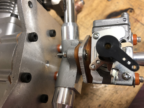
Now with the metering chamber on the bottom, any air or vapor is continuously vented and does not accumulate. Since this modification, the engine has purred without incident and is a very pleasant engine to fly.
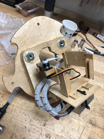
Next I need an engine mount assembly to bolt into the firewall of the Dauntless. The engine mounts with four aluminum standoffs. I bolt this to my engine plate, which is recessed so the prop will be about 1/2" forward of the cowl. Also, the engine mounting plate is skewed to provide a 2 degree right thrust and 2 degree down thrust. Included on my engine mount assembly is a means to attach the throttle servo and ignition module.
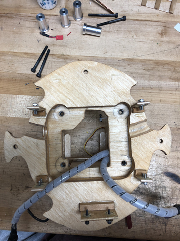
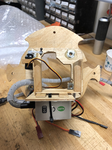
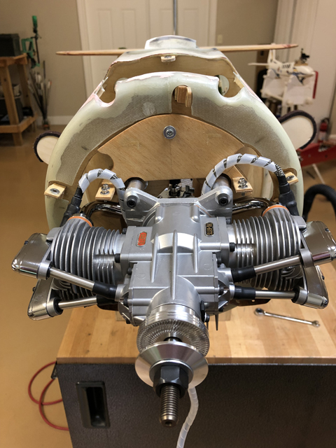
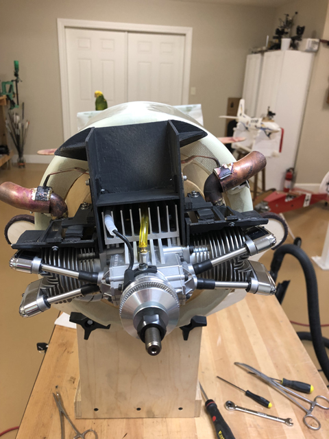
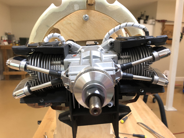
Below are pics of the front and two rear pics of the engine mount assembly. The front view shows the recessed bolting location of the four engine standoffs. Also seen on the front are bolting plates for the exhaust system and engine baffles.
The rear views shows the throttle servo and ignition module. The engine mount assembly bolts to the firewall with four bolts (top, bottom and each side). Cutouts in the mount are to allow airflow to the functional air slots in the Dauntless fuselage.
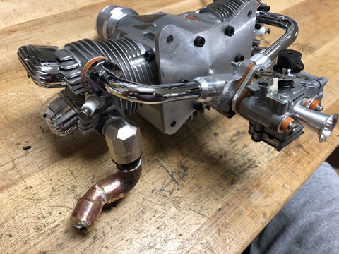
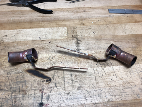
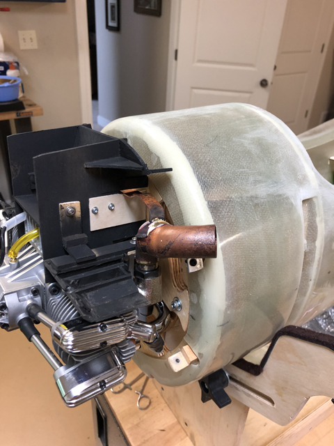
Custom exhaust is then fabricated from the Saito, factory supplied 90 degree exhaust fittings, and copper pipe. The pieces are brazed together rather than soldered since solder will not hold up to the heat of the gas exhaust. This is done so that functional scale exhaust ports can be used on the Dauntless.
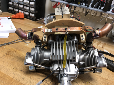
A shroud is then made from 3/4" copper 45 elbows and 3/4" pipe supports. The heat from brazing the supports to the copper elbows gives the elbows a nice scale color. No painting will be required for the shrouds, and they will look great.
A brass plate is then drilled to accept a 1/8" brass tube. This is soldered on and will become an anchor point for the crankcase breather tube. The plate will then be bolted with the shrould supports to the attachment plate on the engine mount assembly.

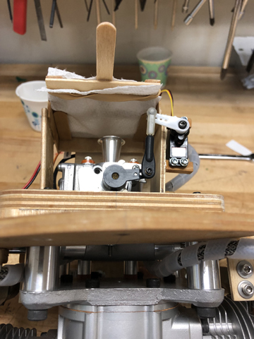
Putting it together:
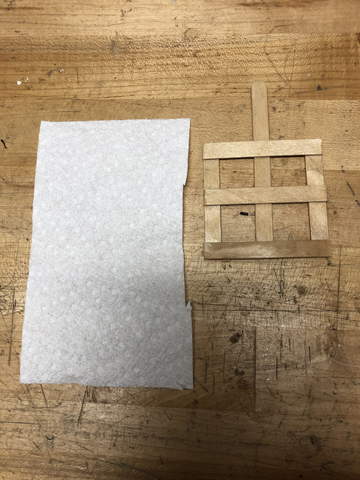
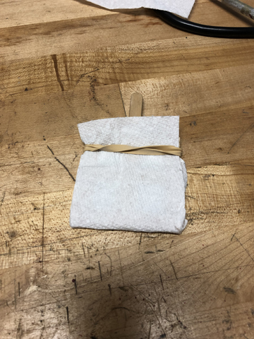
The problem with a rear facing carb that protrudes into the fuse is that it spits a little fuel out of the venturi during engine operation. This can make a mess of the interior. To catch this, an armature is made of popsicle sticks that will hold a small section of paper towel. This is replaced after a day of flying and is easy to access and change.
The assembly is ready to bolt into the firewall. 4 bolts are used to secure the engine mount assembly onto the firewall. Note that three are socket head cap screws, while the one on the right (plane left side) is a hex screw. Also visible on the firewall are the cowl mounting points. The four oval holes in the firewall are ducted to the air exhaust slots on the side of the fuse.
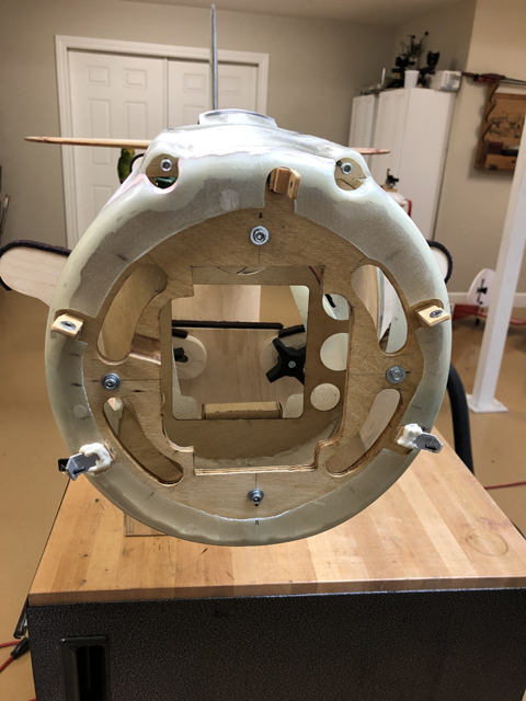
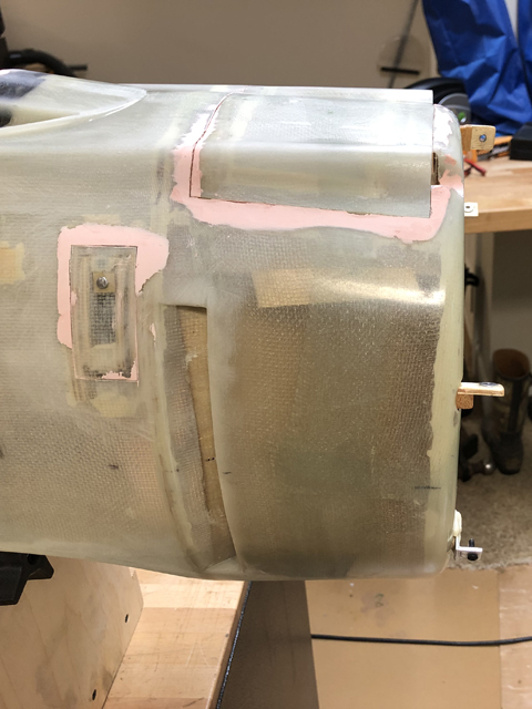
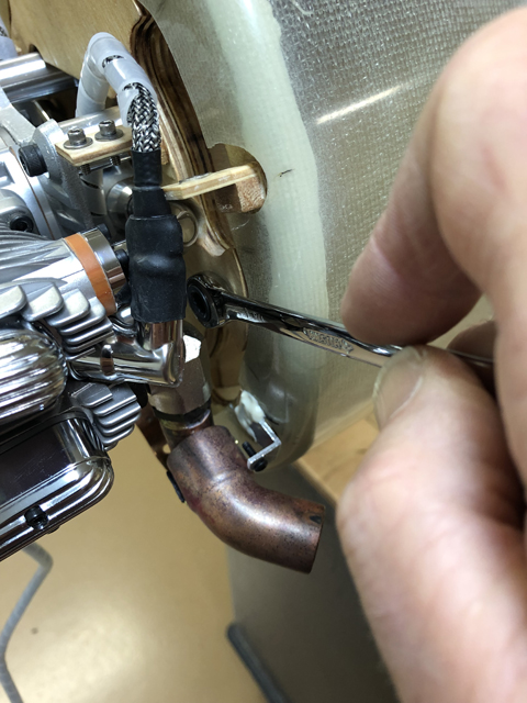
Due to the tight clearance between the engine cylinder and the engine mounting plate, a ratchet wrench is used to secure the hex bolt. A ball driver is sufficient for the remaining three socket head cap screws
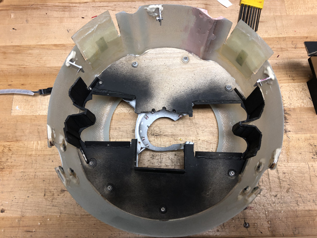
When flying the engine in the Howard DGA (a cowled engine), care was taken to baffle the air to the cylinders. There are three critical areas that need baffling, each cylinder and the crankcase heat sink. The intent of the baffling is to ensure that no air enters the cowl that is not used for cooling. Excessive air inlet that does not flow over the engine will choke the exhaust air flow, reducing cooling. There is a gap between the back of the cowl and the front of the fuse that will provide some air exhaust. The functional air slots on the fuse sides will be used as well to help exhaust hot air from around each cylinder. The airflow over the engine crankcase heat sink will be isolated from the air flow over the cylinders. This will prevent excessive air flow from the heat sink from impeding cylinder cooling.
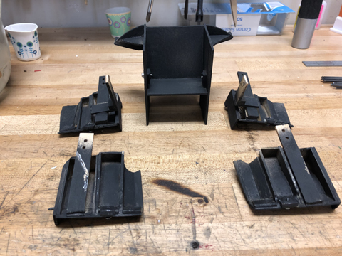
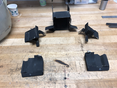
The two baffles in the foreground are for the top of the cylinders. The three in the back are for the bottom of the cylinders and the heat sink. The second picture shows the cylinder baffles turned over. They are shaped and contoured to flow air around the cylinder, not to just flow to the cylinder. The steps on cylinder baffles hug the cooling fins on the cylinder heads. The front of the cylinder baffles are also angled at 45 degrees to increase the air volume over the cylinder heads:
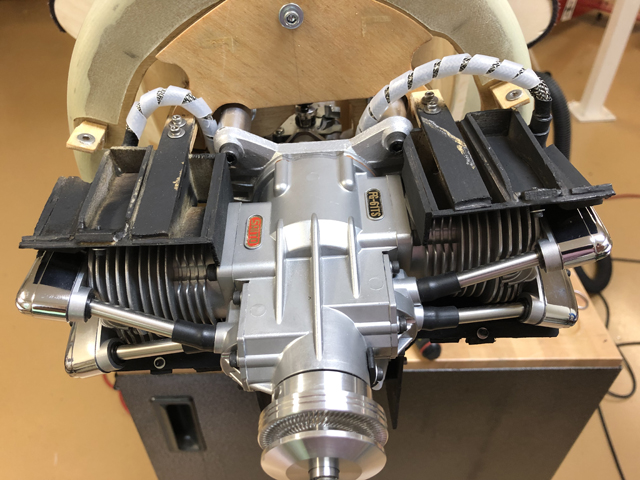
Lower baffles installed:
Upper baffles installed:
The cowling has a front baffle plate that is cut to only allow airflow into the cylinder and heat sink baffle chambers:
A dummy radial is affixed to the front of the cowl baffle plate:
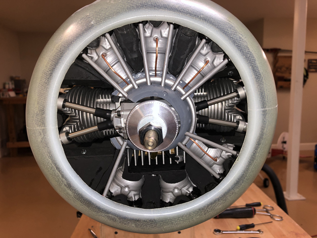
Cover plates are placed on the cowl where the exhaust exits.