It is now October of 2001, five months after making the decision to purchase the
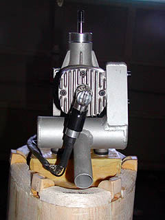
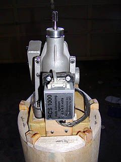
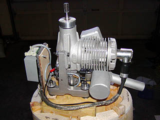
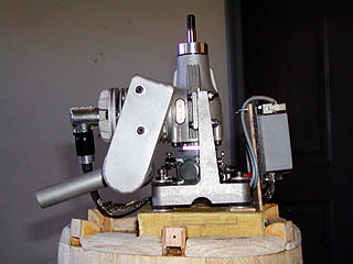
P-47 from Randy. Engine is here and I can't wait to run it! It is a RCS-140
from R/C Showcase. This is a 1.4ci (22cc)
gasoline engine, with electronic ignition and a high-quality pitts-style muffler.
It has roughly the same power as a 1.20 4-stroke glow engine (swings that 16x8 APC
around 9000rpm), which is the upper limit of Top Flite's recommended range, and is
about the lightest-weight gasoline engine made for model
airplanes. Should provide plenty of power, and fits the cowl pretty well (I may trim
the exhaust pipe to only stick out a little... but probably not for the first flight or two).
However adding it, plus all the other
little things like scale retracts, a semi-scale spinner (tru-turn prop-hub), cockpit
kit, pilot, fiberglassed+painted+clearcoated, etc. will add weight to the model.
Good thing it was built light... and by somebody else. Had I been the builder, it would
weigh at least two pounds more! (ask me about my 8-pound
TF Contender, built strong enough
to take a 91FX).
I hope to keep the all-up weight of the P-47 around 11 pounds,
though it may push 12 before it is done. Bright side is... I've heard the airframe
flies light anyway and won't mind the extra weight. Since I want to get into much
bigger warbirds in the future, eventually a B-17 (I have an uncle that was a B-17 pilot during WW2),
I figured the experience gained from the extra wing-loading would be worth it
(I don't need another sport plane).
Several things have been completed at this stage:
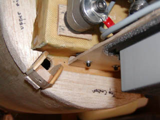
Firewall strengthened and reconfigured for new engine (Carbon Fiber, Kevlar, and additional birch aircraft-ply).
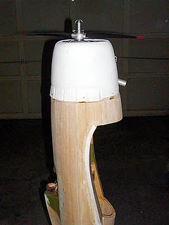
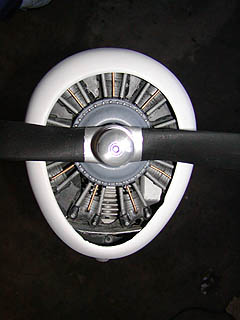
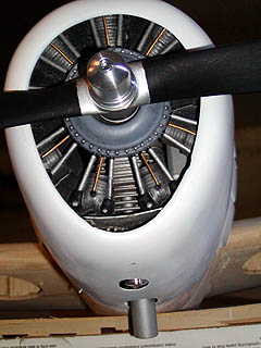
Fiberglass Cowl modified to fit new engine (baffles installed, holes cut for exhaust, cooling, and sparkplug-cap).
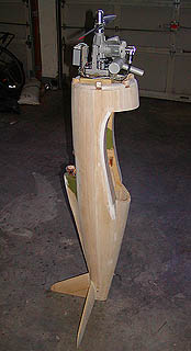
Cowl ring constructed and installed (not sanded quite to shape yet), engine and ignition system mounted temporarily.
Wing filet nearly finished.
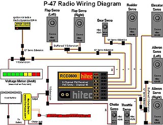
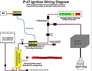
Servo, control-rod, and wiring placement engineered, including engine throttle and choke (servo controlled). All radio gear mounted behind cockpit, all ignition wiring forward of wing-saddle.
LOTS AND LOTS OF SANDING!!! (mainly on the fuse, as parts of it looked more octagonal than
round)
Notes about these images:
Yes, I know the ignition system will be happier if it is grounded on
the engine... not the rubber-isolated mount. I've fixed that since these
pictures were taken.
The open-cell foam on the ignition module has been replaced with
closed-cell foam. I used what I had laying around to engineer the
mounting and to get the cowl fitted.
A bit of downthrust was added, on the recommendation of a couple people.
Easy enough to remove if it proves undesirable. I already have spacers
built for the engine-to-mounting-beam connection if I have to tilt the
engine back up... so that it comes out the center of the cowl opening.
When the cowl is fastened down on all sides (4/40 nylon bolts into the
tapped hardwood blocks), the engine thrust-plate is centered in the
opening... unlike one of the photos below.
In the side-profile photos, the model is not as precariously balanced as
you might believe... it is actually quite stable there. An additional
tiny red shim was added under the keel to make it balance more toward the
vertical stab.
The wiring diagrams were created with a program called "NetViz". It
is designed for documenting computer-networks, but it worked ok for this
task. Far more complicated than any wiring I had done before, so I wanted
to write it down so I could remeber exactly what went where.
