1/6/2011
Nose Gear and Parachute Parts
This update has lots of machine parts in it. I was joking with Jerry the other day and told him that should the unthinkable ever happen and the bird goes down and there's a fire, no matter how bad it looks, we're running after it with fire extinguishers and to try to 'save the fiddly bits'. I'm not kidding when I say, there is twice as much time in making all the small machine parts, versus making the fiberglass parts. Granted it would go a bit faster the second time around, but still, each of the little parts you're about to see, I need to figure out from scratch, sketch them out, then machine and make them. Each 'cut', or 'operation' as it's called, must be setup, clamped, measured, cut with multiple passes, measured several times as you get close to your dimensions, and then a 'finish pass', that removes the last little bit and leaves a good finish on the part.
Each individual part you see here will usually have 15 to 20 'operations' on it, with each step taking 10-20 minutes each. Start doing the math with what you'll see, and you can see that it takes quite a while to make these things. Don't get me wrong, I find it really fun, and enjoy the process, but you just have to accept it's going to take some time to custom make the metal parts. I'll put on some headphones and listen to some music and the next thing I know it's several hours later and I've got another part done.
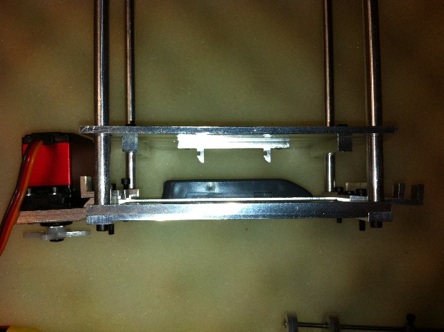
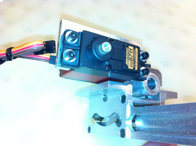
Last time I showed the basic frame of the parachute chucker. Here it is all assembled now, including the custom made servo mount that will release the floor. Not pictured here are the springs that will be on each of the 4 posts.

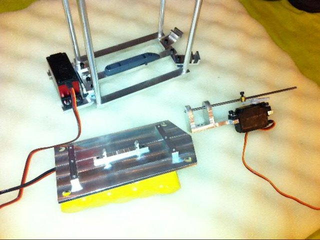
Here's the same parts shown, plus the bracket that also holds a servo, that will be the 'cut-a way' part of the parachute system. The complexity of the system has gotten crazy, but it all seems needed. In total, it's got 5 servos involved, including the functions of door locking pins, air cylinders to open the doors, floor release to throw out the chute, and a cut-a way servo, all of this organized by an electronic system by Dan Gill, from Details 4 Scale.
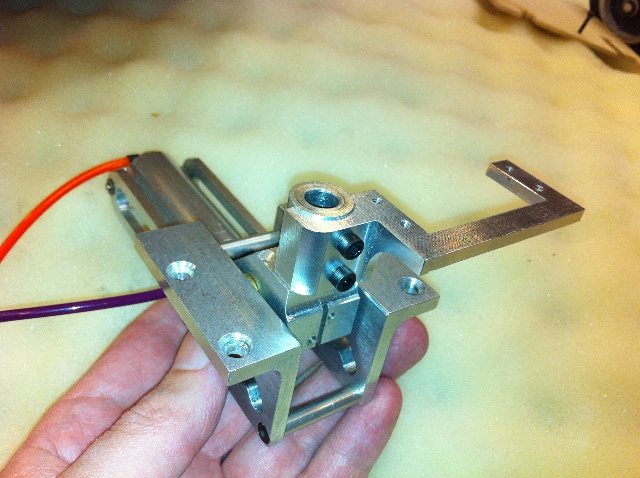
Next up is the work on the nose gear area. The prototype flew with this same retract and basic strut, but no gear doors, and none of the extra scale bits. Also on the prototype I used the stock 'pull-pull' cables for steering. On the last time out with the prototype, I hit a crack in the runway, and it slightly sprung the gear rearwards, and messed up the clevis that was holding the cable. I'm trying to make this thing as rock solid as possible for the day to day rigors of many jets meets per year and also maintenance friendly, so I can work on it in a motel room, if needed. So.. With all of that in mind, I decided to modify the gear so I could mount the steering servo directly to the retract, and I'm pleased how this turned out. See below the mount I figured out, without the servo in it.
Here's the same shot, whit the servo mounted, and the gear in the 'down' position.
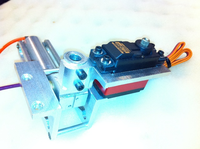
Here's the gear in the retracted position, showing the servo clearance to the mount.
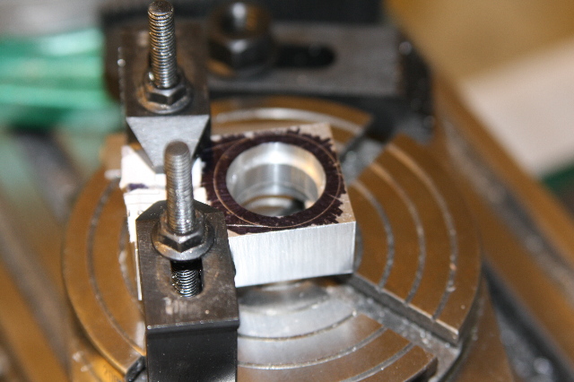
Next up was the angled strut on the nose gear, that on the full size is what actually does the retraction motion. This strut also is related to one of the nose gear doors. I had a fundamental problem in designing this strut and it's attachment. On the full size, only the bottom of the strut has the moving part for nose wheel steering. On mine, the entire strut turns. So, I needed the attachment point to be able to rotate around the strut, so I could steer 'through' it. This photo shows the key part to this setup being clamped on the rotary table to cut the outside round shape on about 200 degrees of the outside.
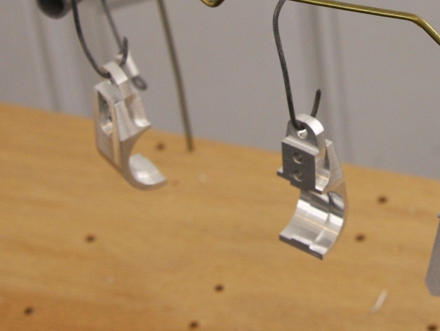
This photo reveals how tough these parts were to make. I needed a single collar that could clamp around the strut, and stay in place. If you look to the inside of the round part, you'll see a ridge. This goes in a groove I cut into the strut. The bear of this was they needed to mate up exactly the same so they could look like one part, but yet have a perfectly round interior. And no, you can't make the part then cut it in half. The metal you'd loose on the cut would blow the roundness of the hole. This shot was just before powder coating, and I'm quite proud of how neat this small part turned out, given it's complexity. It started out from a solid bar of aluminum.
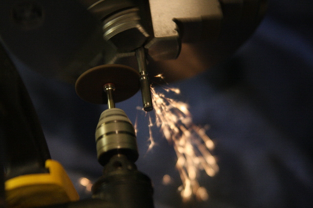
A pin in the collar part will be retained by 'e' clips on both sides. I've heard people have had a hard time with these, and after a bit of trial and error, I've gotten a decent system of making these. I put the steel rod in the lathe, and then clamp my Dremel into onto the tool post. Then I can take a cut off wheel and precisely control how deep and wide a grove I cut into the rod and where it's placed.
Here is the entire gear assembly shown in the retracted position, albeit upside down. (Nose gear door shown would be on the bottom of the plane)
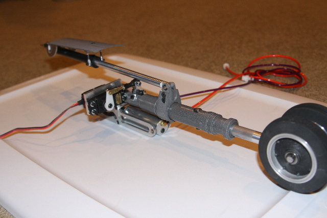
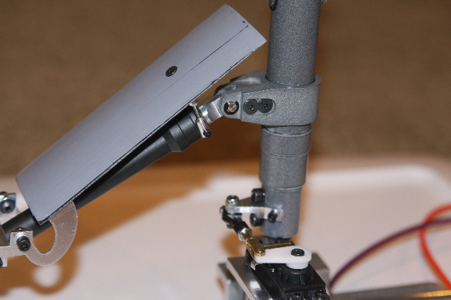
Close up of the collar I was speaking about above, it's connecting cylinder, and also the nose steering servo, it's linkage and the tiller arm that was made to fit the shaft. You'll see here, that I could not complete the steering, until I completed the cylinder works just above it. That was needed to find out what clearance I had, because I had wanted to make the tiller arm on the steering as long as I could so I had the best leverage I could get.

Here's a close up of how all these parts look, when in the 'down' position. (Once again upside down) You can see here how the collar, and dummy cylinder works in relation to the main nose gear shaft that must pivot through it, to steer properly.
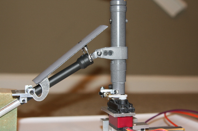
The last update photo, shows some of the complexity of angles to get the retraction to work properly and also pull in and seat the aft nose gear door. The bracket you see to the far left is a good example of what I was speaking about above, so that parts that can be maintained. If I just remove 2 mounting bolts, the entire sub assembly of hinges, door, and strut all come out as one unit. Next up is working on the main nose gear doors, and hinging the canopies on top.
Head back to the Main Page